Garden Watering Automation
January 2017
Overview
I already have a quite extensive system of pipes set up to water my plants. The problem is that it's best to water plants low and slow in the morning under mulch, rather than high and fast in the evening with a beer and hose.
Watering early in the day is better for the plants from a mildew and fungal perspective as water doesn't sit against the plants for the whole day. Watering just before dawn also conserves moisture as it gets a chance to soak in and get to the roots before the sun is up.
With this in mind, I decided to automate my garden watering system using my Raspberry Pi so that I could water my garden at the right time of day from anywhere on the planet.
I should also point out that there is plenty of inspiration out there. I've found lots of great projects online which tackle this problem in similar ways. Open Sprinkler Pi really took my fancy, but I realised that because I already had a Pi and Grove, I didn't really need to buy a seperate controller.
If you'd like to use any of the code for this project, you can download it on github.
Update: January, 2018
I've recently modified my setup a little. While the plumbing is still the same, I've removed the GrovePi from the equation as it was becoming unreliable and would only work with frequent resets. Instead, I've used the ruby gem, RPI_GPIO, to directly connect my Grove Relays to the Raspberry Pi. This has had the added benefit that all the code for the project can be consolidated into the one scheduler.rb file instead of needing to make calls out to companion python scripts.
There are a few issues with the RPI_GPIO gem, the largest being that you can't install it on non-Raspberry Pi machines, but the improved reliability offsets this inconvenience. I'm sure I'll be able to find an alternative GPIO controlling gem that resolves this problem also.
For this project, I have used:
- Raspberry Pi
- ~~GrovePi+ board~~
- Seeed Studio Grove relay
- Some 25mm solenoids
- A 240 > 24V transformer (this is the bit that worries me)
- Some 7 core irrigation wire.
- Irrigation wire connectors
- Existing watering system (made primarily with 19mm PVC poly pieces)
- Pope 25mm 3 outlet manifold
- 3 x lengths of rigid BSP pipe (thicker, solid pipe with male threaded ends)
- Assorted BSP 1" bits and pieces - I would recommend staying away from the "nut and tail" type joins as they seem quite hard to get to stop leaking.
If you're considering this yourself, a word of warning
This probably won't save you money. It may not even save your garden.
For me, excluding the cost of the Pi and Grove (which I already had) the total cost of this experiment has probably been about $180AUD allowing $150 for plumbing supplies, $30 for additional power boards, ethernet cables etc. This actually isn't insane given that it will easily cost about $100 to buy a controller at your hardware shop and then you'll have to hand over more for solenoids, pipes, wires etc.
For me, the most important thing I've learnt through this project is the consequences actions can have when you move from the digital world into the real world. Most web developers and designers play in a world where the worst that can happen to them personally as a result of a failure in their decisions is that they get less conversions on a transactions, or their site goes offline for a few hours.
In this project, making a mistake could cost me my garden (which could die or be drowned) or damage the foundations of my house (if the manifold or pipes burst and spew water out, underneath my house, for days while I'm away from home).
Still, I'd recommend this regardless. It's been great fun. I hope if you do go down the automation route that this helps in some way.
This document is broken into four sections for easy reference, and the code is really simple. I'll try and keep the software concerns seperate as I build this project out over time so you can pick it up and use what you need without needing to understand lots of complicated code. I'll also try and remember to comment lots so it's easy to understand. Thank you to all the other open source projects that do this also! It's only because of the forethought and generosity of time others have given that I've been able to learn how to do any of this.
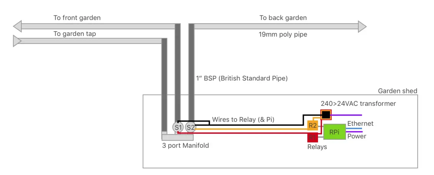
Plumbing
Using my existing watering system, essentially my goal was to create an intelligent hub through which the water flowed when I wanted to.
To do this, the mains water goes into the manifold, where it is then stopped by the solenoids. When the solenoid is opened by the relays attached to the RPi, the water flows. By default, the relays are closed and take electric current to keep them open. This works for me because it means that in the event of a power-failure I won't flood my house.
Although I felt quite confident about the plumbing side of things, one of the things I learnt through this process is that it's actually really hard to do plumbing if you care about slow drips. Also important is to consider that this is one of the few projects where you're combining water and electricity - two things that shouldn't really meet unless you're interested in entering the Darwin awards.
My first attempt at building out the manifold used 19mm Poly pipes and joiners to connect things. This didn't work so well and burst just before I proudly demonstrated my new fool-proof internet-powered garden watering system to Andy Carson. The mains water pressure was too much for the plastic clips I used.
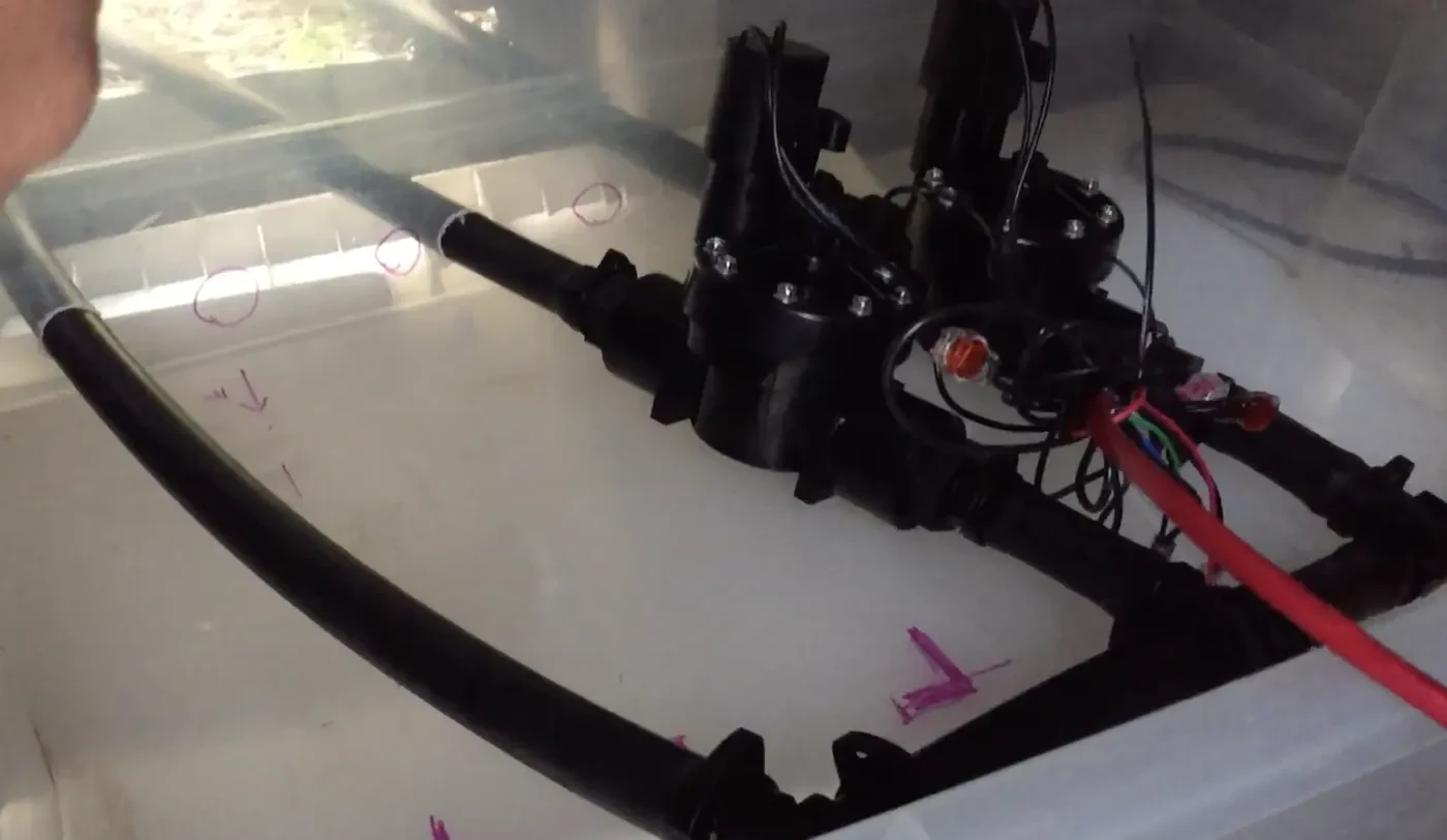
To solve this, I decided to replace the entire manifold and feeder system with more study rigid BSP pipes and steel screw-tightened clips wherever I moved into poly pipe.
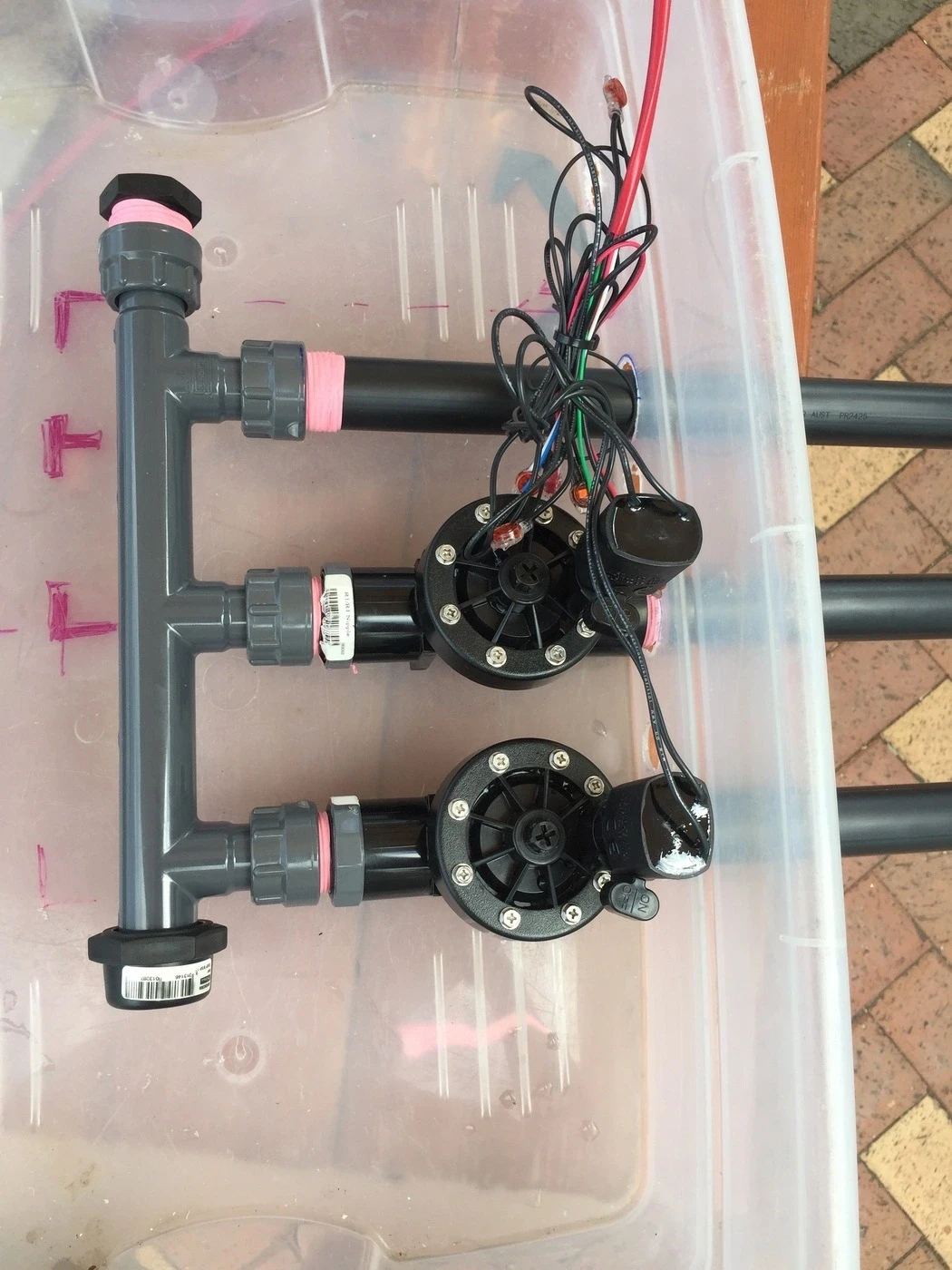
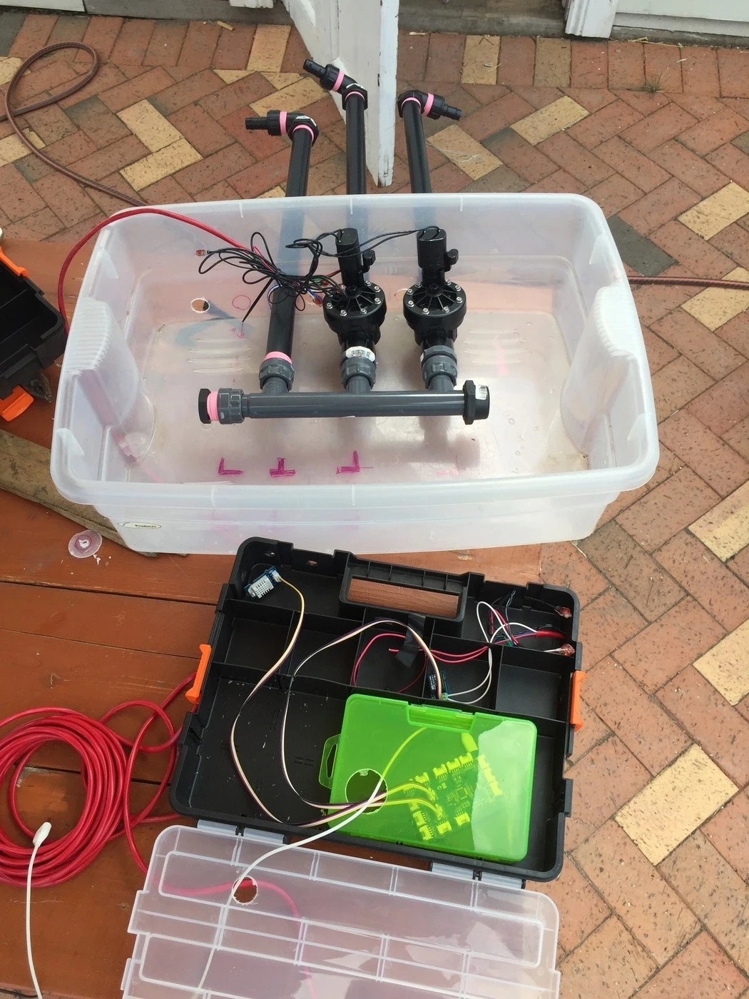
Here you can see all the pieces assembled and in their box in preparation for going into my shed.
Once I put this in, I found that there was then an issue with the "Nut and Tail" joints I'd used at the end of the BSP. They leaked - I even cracked the plastic on one hand-tightening it so it wasn't going to last long. In the picture below you can see the failed unit on the bottom, and the replacement on the top.
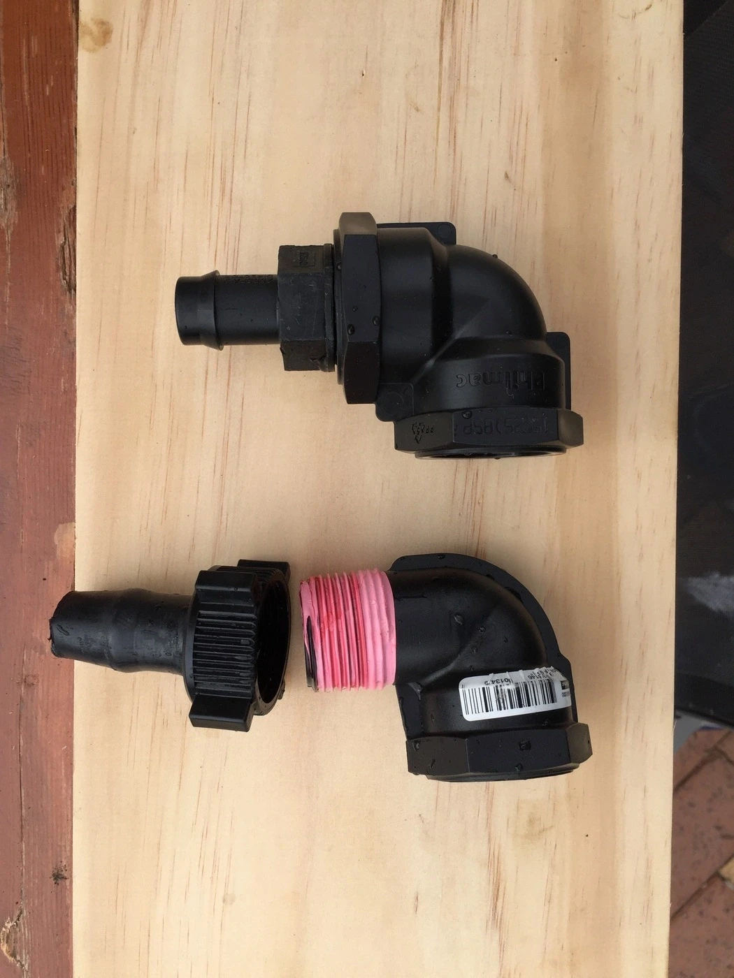
This is because it's difficult to get a tight enough seal as the joint is made in two pieces with a washer. I solved this buy replacing the Nut and tail with a BSP female threaded joint and one piece 19mm reducers.

Once I had this all assembled, I set up a cron job to trigger my watering system on and off for a minute at a time in order to pressure test and rock/jerk the system around a bit. Turning water one and off with a solenoid is quite a violent process (you'll hear it - there is quite a bit of pressure involved in mains water) and I think this is what caused my first iteration to fail. Turning it on and off rapidly means you get to i) see if it leaks and ii) hopefully accelerate any failure so you can fix it before you come to rely on it working properly.
Electronics
From an electronics perspective, it took me a while to figure out what was needed. Thanks to my Grove Pi kit, I had a relay, but just no real idea how to use it. Also no idea how to avoid electrocute myself.
Enter many hours of youtube research and videos.
Through this research I found that I'd need to do the following:
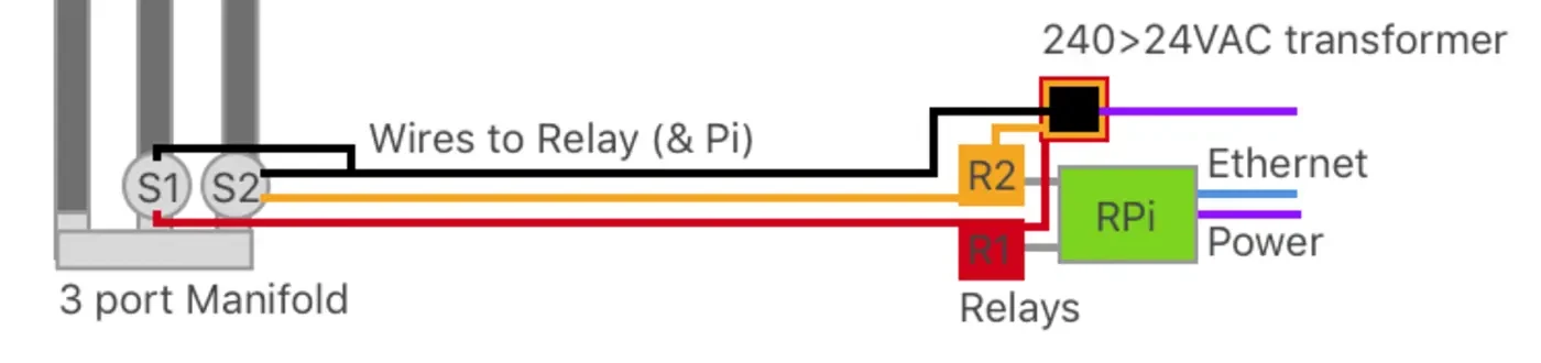
- Connect the black wire to one of the cables from each solenoid (they have two each) and also to the transformer. This is the "power wire" and provides one half of the circuit needed to turn on the solenoid.
- The second wire (I chose red and white (shown as yellow) provides the "control" wire.
- The "control" wire is fed through the relay and then back to the second wire from the transformer. This way, when the relay is activated, the circuit is completed and the solenoid is able to activate (allowing water to flow).
Because water is being used in close proximity to electricity here, I wouldn't recommend doing this unless you felt pretty confident in your knowledge. There are a few things I did to keep myself safe.
- Most importantly: I did not plug in the transformer until I was sure there were no exposed wires
- I made sure that I put electrical tape over the ends of any exposed wires before I plugged anything in.
- The transformer I used for this project takes the 240VAC (240 Volts Alternating Current) found in an Australian powerpoint and drops it down to 24VAC. This is a much lower voltage (garden lights use 12VAC so that you don't die if you cut through a wire), but I'd prefer to be safer than sorry. Supposedly a 24V current can kill you if it gets under your skin.
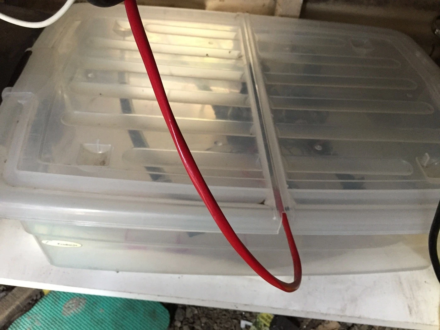
- I put the solenoids (which were the piece most likely to come into direct contact with water) were inside a plastic tub. This way, if the solenoid failed or there was a leak, water wouldn't spay all over my shed, and would just dribble over the floor (turned out this safety feature was used :-) ).
- I ended up using these nifty little waterproof wire connectors. They are one used only, but flood themselves with a gel when used to create a water proof seal on the wires. This is important as although the solenoids shouldn't get wet when they're being used, as I found when I flooded mine, they can sometimes.
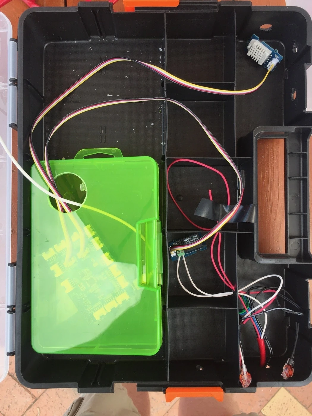
Putting it all together I ended up with a situation like this. Here you can see:
- Raspberry Pi and Grove Pi board on left inside green box.
- Input compartment bottom right for 7 core irrigation wire.
- First relay connected in it's own compartment (white wires)
- Wires taped waiting for second relay to arrive from Little Bird Electronics.
- Temperature/humidity sensor top right (for a seperate project)
- Holes for ethernet and USB-power to come into the green box to power and control the Raspberry Pi.
Code
For me there were are a few challenges I have/will faced in this project.
- Not that familiar with Python. Everything to do with IoT seems to be in Python. I have more experience in Ruby so this could trip me up.
- I'm still learning raspberry pi/Unix.
Method & Progress
To help myself overcome some of these issues, I've broken the challenge down into some smaller steps to knock over one at a time. I'll keep this list updated as I go.
- [X] Be able to turn on and off the relay using a switch.
- [X] Be able to turn on and off the relay using a script, keeping it on for a few seconds, then turning it off.
- [X] Be able to turn the relay on for a period of minutes, then off again.
- [X] Be able to turn the relay on at a defined time for a period of time (eg. at 3pm for 20 mins). Stop scripts from stomping on each other.
- [ ] Be able to do the same thing with more than one system.
- [ ] Be able to reliably start and stop smaller watering jobs (eg. 10 minute watering session) via my mobile phone - I currently use SimpleSSH for iOS but am keen to give Prompt2 a go.
- [ ] Ability to control inline solenoids downstream to water specific beds for less time than others.
- [ ] MAYBE: Integrate with a home assistant so that I can verbally say "water my garden for n minutes" and actually have that work…because we live in the future (also gives me a good reason to buy said assistant)
- [ ] MAYBE: Integrate my timing with Google Calendar to use that to turn on and off the system using named calendar events.
- [ ] MAYBE: Deliver push notifications to my phone when watering is started, stopped or if there is an error.
Update from 2023: I've well and truly gotten past all of this 👆 and I invented something far more durable and reliable. Video demo coming soon.